


Automatic Street Light Science Kit
Automatic Street Light Science Kit
𝐒𝐜𝐢𝐞𝐧𝐜𝐞 𝐊𝐢𝐭|𝐀𝐮𝐭𝐨𝐦𝐚𝐭𝐢𝐨𝐧|𝐀𝐠𝐞𝐬 𝟏𝟓+ 𝐲𝐞𝐚𝐫𝐬|𝐄𝐥𝐞𝐜𝐭𝐫𝐢𝐜𝐚𝐥 𝐏𝐫𝐨𝐣𝐞𝐜𝐭
Couldn't load pickup availability
- Free Shipping
- Easy Assemble
- Cash On Delivery
Product Description
Product Description
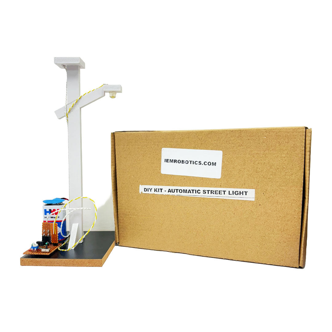
Do you want to know how 𝐀𝐮𝐭𝐨𝐦𝐚𝐭𝐢𝐜 𝐒𝐭𝐫𝐞𝐞𝐭 𝐋𝐢𝐠𝐡𝐭 𝐒𝐜𝐢𝐞𝐧𝐜𝐞 𝐊𝐢𝐭 works? Learning more about how this Automatic Street Light 𝐒𝐜𝐢𝐞𝐧𝐜𝐞 𝐊𝐢𝐭 is exciting and simple. A Light Dependent Resistor (LDR) makes it work without any help from people to turn the lights on and off at night and during the day. The LDR knows when it's dark, making the light shine brightly when the sun goes down. This 𝐚𝐮𝐭𝐨𝐦𝐚𝐭𝐢𝐜 𝐬𝐭𝐫𝐞𝐞𝐭 𝐥𝐢𝐠𝐡𝐭 𝐩𝐫𝐨𝐣𝐞𝐜𝐭 is great for 11th or 12th graders and first- or second-year college students. You can learn about circuits and how technology can help us save energy in our daily lives with some simple parts and some help.
What's in the Box?
What's in the Box?
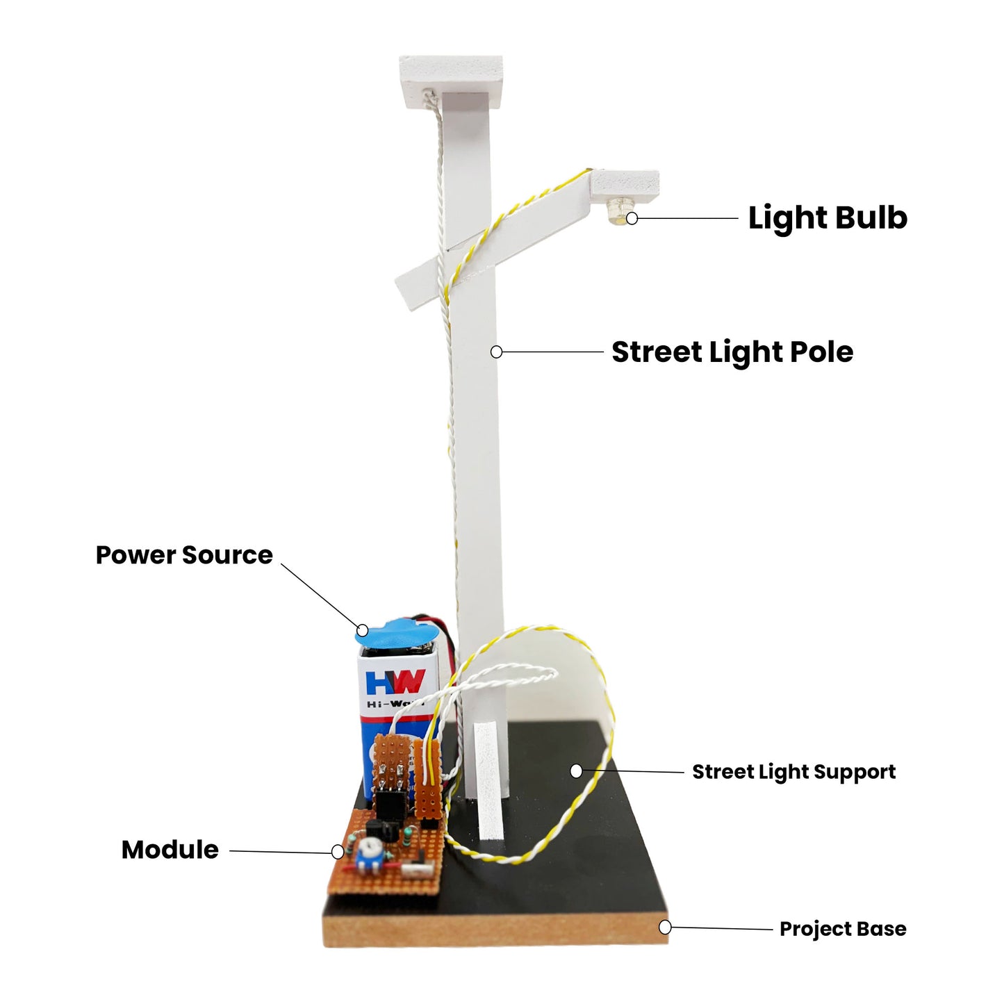
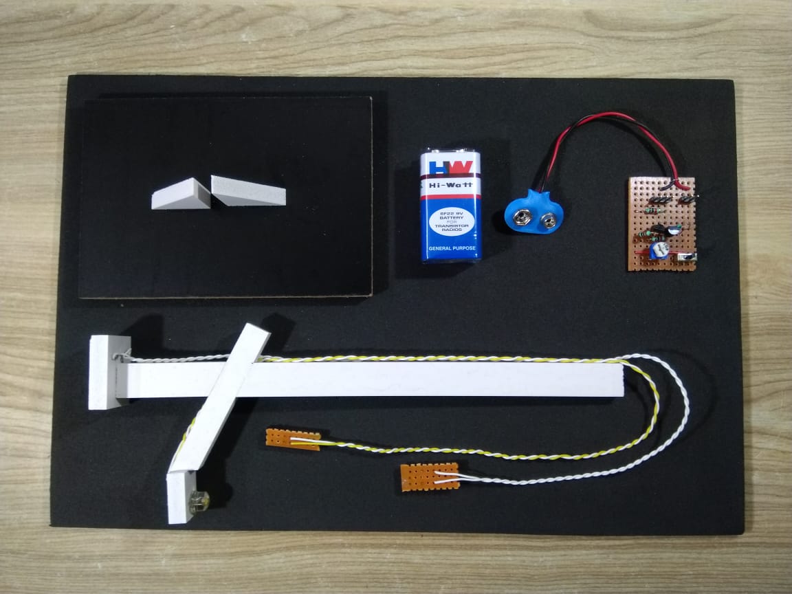
• Main Component: Light Dependent Resistor (LDR)
• Transistors: 2 x BC547 (NPN)
• Resistors: 3 x 1K, 1 x 100K
• Light Source: LED bulb
• Power Supply: 9V Battery
• Base Material: Wooden Board, WPC Board
Shipping & Return
Shipping & Return
• Order Processing typically takes 𝟐𝟒-𝟒𝟖 𝐁𝐮𝐬𝐢𝐧𝐞𝐬𝐬 𝐇𝐨𝐮𝐫𝐬, during which orders are picked, packed, and prepared for shipment.
• 𝟕 𝐝𝐚𝐲𝐬 𝐆𝐮𝐚𝐫𝐚𝐧𝐭𝐞𝐞𝐝 𝐑𝐞𝐩𝐥𝐚𝐜𝐞𝐦𝐞𝐧𝐭 from the date of delivery.
• 𝐅𝐫𝐞𝐞 𝐃𝐞𝐥𝐢𝐯𝐞𝐫𝐲 on orders above ₹𝟗𝟗𝟗/-
Share
Republic Day SALE Extra 10% OFF | REPUBLIC10
Technical Specification
𝐀𝐮𝐭𝐨𝐦𝐚𝐭𝐢𝐜 𝐒𝐭𝐫𝐞𝐞𝐭 𝐋𝐢𝐠𝐡𝐭 𝐒𝐜𝐢𝐞𝐧𝐜𝐞 𝐊𝐢𝐭 for Students 15+ years
𝐀𝐮𝐭𝐨𝐦𝐚𝐭𝐢𝐜 𝐎𝐩𝐞𝐫𝐚𝐭𝐢𝐨𝐧 𝐰𝐢𝐭𝐡 𝐋𝐃𝐑
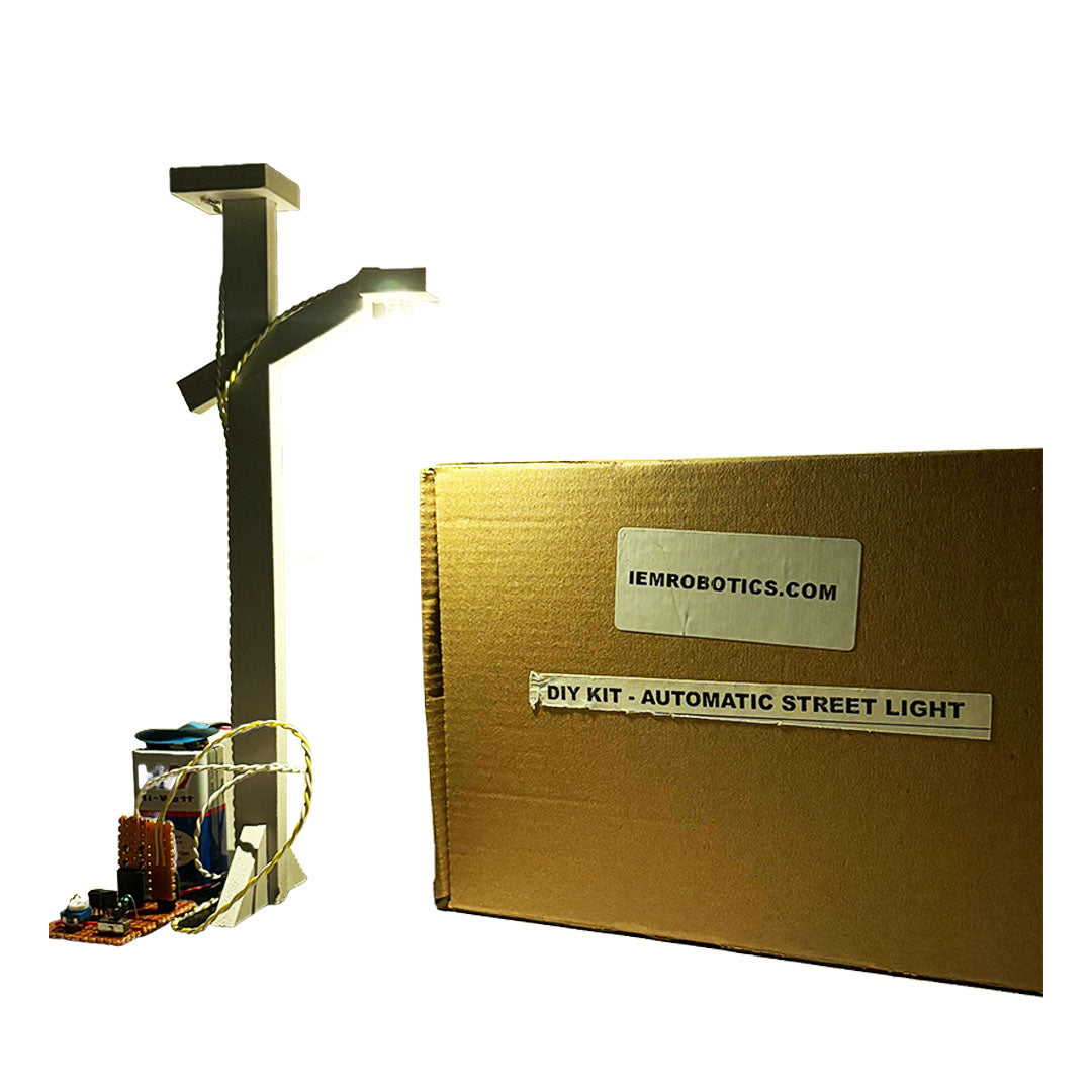
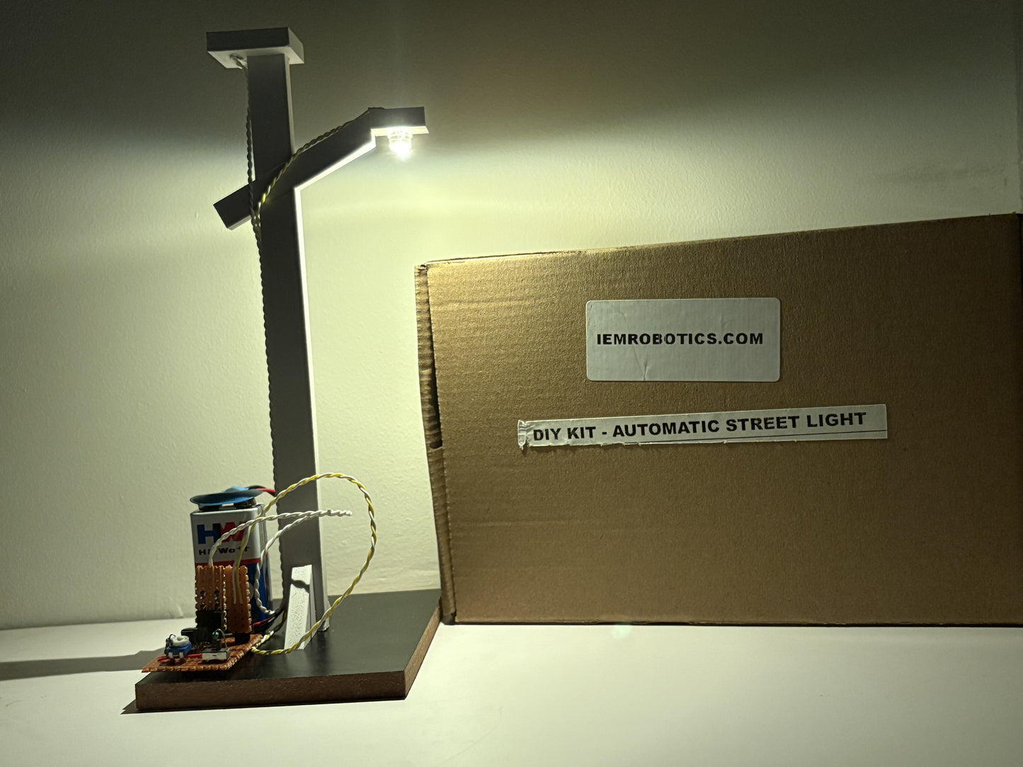
Uses a Light Dependent Resistor (LDR) to sense lighting conditions, allowing the light to switch on at night and off during the day, no manual effort needed.
𝐄𝐧𝐞𝐫𝐠𝐲 𝐄𝐟𝐟𝐢𝐜𝐢𝐞𝐧𝐭 𝐃𝐞𝐬𝐢𝐠𝐧
Automatically adjusts lighting based on outdoor brightness, reducing unnecessary energy usage and promoting sustainability.
𝐄𝐚𝐬𝐲-𝐭𝐨-𝐀𝐬𝐬𝐞𝐦𝐛𝐥𝐞 𝐊𝐢𝐭
Comes with all required components, providing a straightforward setup for beginners interested in circuit technology.
𝐄𝐝𝐮𝐜𝐚𝐭𝐢𝐨𝐧𝐚𝐥 𝐅𝐨𝐜𝐮𝐬 𝐨𝐧 𝐄𝐧𝐞𝐫𝐠𝐲 𝐂𝐨𝐧𝐬𝐞𝐫𝐯𝐚𝐭𝐢𝐨𝐧
Demonstrates how technology like LDRs can be used to conserve energy, perfect for environmental science projects.
No Reason to Delay, Buy from iemrobotics.com
Why You Should Buy 𝐀𝐮𝐭𝐨𝐦𝐚𝐭𝐢𝐜 𝐒𝐭𝐫𝐞𝐞𝐭 𝐋𝐢𝐠𝐡𝐭 𝐒𝐜𝐢𝐞𝐧𝐜𝐞 𝐊𝐢𝐭?
𝐆𝐫𝐞𝐚𝐭 𝐟𝐨𝐫 𝐒𝐓𝐄𝐌 𝐋𝐞𝐚𝐫𝐧𝐢𝐧𝐠
Encourages learning about Science, Technology, Engineering, and Math (STEM), making complex concepts simple to understand.
𝐈𝐧𝐭𝐞𝐫𝐚𝐜𝐭𝐢𝐯𝐞 𝐋𝐞𝐚𝐫𝐧𝐢𝐧𝐠 𝐄𝐱𝐩𝐞𝐫𝐢𝐞𝐧𝐜𝐞
Practical hands-on project that provides a deeper understanding of LDR sensors and automatic control systems.
𝐂𝐨𝐦𝐩𝐚𝐜𝐭 𝐚𝐧𝐝 𝐏𝐨𝐫𝐭𝐚𝐛𝐥𝐞
Designed to be compact and lightweight, allowing easy storage or display as a science project once completed.
𝐏𝐞𝐫𝐟𝐞𝐜𝐭 𝐟𝐨𝐫 𝐒𝐭𝐮𝐝𝐞𝐧𝐭𝐬
Ideal for 11th and 12th graders or early college students, this kit offers hands-on learning in electronics and circuitry.
Simple operation.
Easy assembly, limited documentation.
Minor component quality.
Basic science features.
Student-friendly DIY project.